For cooperation and more details, feel free to email us or call directly for consultation.

Home > News & Blog > Knowledge > Common RF Welding Defects: Burn Marks, Weak Seals and Uneven Welding
Common RF welding defects include burn marks, weak seals, uneven welding, incomplete fusion, material deformation, and inconsistent weld seams. These problems often result from incorrect RF power, unsuitable welding time, uneven electrode pressure, poor electrode alignment, inappropriate material selection, or inconsistent material thickness. To improve weld quality, manufacturers should check the welding parameters, inspect the electrodes and fixtures, verify the condition of the thermoplastic material, and maintain consistent pressure and cooling conditions throughout the welding process.
Radio frequency welding defects can often be corrected by adjusting power, pressure, welding time, electrode geometry, and material positioning. However, the correct solution depends on the defect type, the material being welded, and the design of the welded joint.
RF welding defects are imperfections or inconsistencies that occur during radio frequency welding, a process that uses high-frequency electromagnetic energy to generate heat inside suitable thermoplastic materials. These defects can affect seal strength, appearance, dimensional accuracy, leak resistance, and the service life of the finished product.
In industrial production, the most common RF welding defects include burn marks, weak seals, uneven welding, incomplete fusion, excessive material thinning, and distorted weld seams. Identifying the underlying cause helps manufacturers select appropriate welding techniques and improve process consistency without unnecessarily increasing production time or material waste.
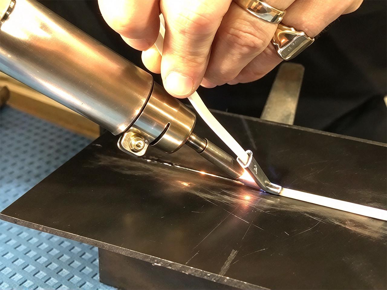
Radio frequency welding, also called RF welding or high-frequency welding, is widely used to join compatible thermoplastic materials such as PVC and certain polyurethane formulations. The welding machine applies an electromagnetic field to the material between an electrode and a supporting platen. Molecular movement generates heat, softening the material so that pressure can form a welded joint.
The final weld quality depends on several interacting factors.
RF power determines how quickly the material heats during the welding process. Excessive power can cause localized overheating, discoloration, material degradation, or burn marks. Insufficient power may prevent the material from reaching the temperature required for effective fusion.
The correct power setting depends on the material formulation, material thickness, electrode area, weld geometry, and machine configuration.
Welding time controls how long RF energy is applied to the thermoplastic material.
If the welding cycle is too short, the material may not soften sufficiently to form a strong seal. If it is too long, the material may overheat, become excessively thin, or develop surface damage.
Manufacturers should establish a suitable welding window through controlled trials rather than relying on a single time setting for every product.
Electrode pressure helps maintain contact between the materials and the welding tooling. Uneven pressure can produce inconsistent heating and material flow across the weld seam.
Low pressure may result in incomplete fusion or weak bonding. Excessive pressure can squeeze softened material out of the joint, reduce local thickness, or distort the finished product.
Misaligned electrodes can distribute pressure unevenly and produce inconsistent weld widths. This problem is especially noticeable when welding long seams, curved profiles, multilayer components, or products with narrow sealing areas.
Accurate electrode positioning and a stable fixture help maintain uniform contact across the welding area.
Not every thermoplastic material is suitable for RF welding. Materials differ in their dielectric properties, which influence how they respond to the electromagnetic field.
Material formulation, plasticizers, coatings, surface contamination, and layer structure can also affect the welding process. Inconsistent material thickness may cause variations in heating, pressure distribution, and material flow.
Before changing machine settings, manufacturers should verify that the selected thermoplastic materials are compatible with the intended RF welding technology.
Burn marks are among the most recognizable RF welding defects. They may appear as dark spots, brown discoloration, melted edges, blistering, or visibly damaged material near the weld seam.
Burn marks caused by overheating may look similar to marks caused by arcing, but the corrective actions can differ. Manufacturers should determine which mechanism is responsible before changing the process.
Reduce excessive energy input. If the material is overheating, adjust RF power or shorten welding time in controlled increments. Confirm that the revised settings still produce an adequately strong seal.
Inspect for electrical arcing. Check the electrode, insulating components, material positioning, and machine setup for signs of discharge. Clean or replace damaged tooling and verify that the equipment is configured correctly.
Improve electrode contact. Confirm that the electrode sits evenly against the material and that the applied pressure is consistent throughout the weld area.
Check the material. Verify thickness, surface condition, and material formulation. Contamination or unexpected changes between material batches can contribute to inconsistent heating.
Review the electrode design. Sharp edges, unsuitable profiles, or localized pressure concentrations may contribute to defects. Adjustments should preserve the required weld geometry and sealing performance.
Increasing pressure is not a universal solution for burn marks. If the underlying problem is electrical arcing or excessive energy input, pressure changes alone may not resolve it.
Weak seals occur when the welded joint cannot withstand the mechanical load, pressure, flexing, or handling required in its intended application.
The seam may look acceptable on the surface but separate during peeling, tensile testing, inflation, or leak testing.
A weak weld does not always indicate insufficient power. If the material is incompatible with RF welding, increasing power may damage the surface without producing a reliable bond.
Establish the correct welding parameters. Adjust RF power and welding time systematically while keeping other variables stable. Record the settings and test the resulting weld strength.
Verify material compatibility. Confirm that the material formulation is suitable for radio frequency welding. For multilayer products, check whether coatings, adhesives, reinforcement fabrics, or barrier layers interfere with fusion.
Maintain consistent pressure. Inspect the pneumatic or hydraulic system, electrode parallelism, and fixture stability. Pressure should be distributed evenly across the intended weld area.
Review the cooling stage. Some RF welding applications require the material to remain under pressure while it cools and solidifies. Premature release can contribute to distortion or reduced joint integrity.
Remove contamination. Check for dust, oil, moisture, release agents, or other substances between the surfaces. Use a cleaning method compatible with the material.
Perform strength testing. Use an appropriate peel, tensile, burst, or leak test based on the product's function. Visual inspection alone cannot confirm that a welded joint meets its performance requirements.
Uneven welding occurs when different sections of the same seam show inconsistent appearance, width, thickness, or bonding strength. One section may be fully welded while another contains weak spots or incomplete fusion.
This defect is common in products with long sealing lines, complex shapes, or large electrode contact areas.
Check electrode parallelism. Inspect the electrode and lower platen to ensure they meet evenly. Correct misalignment before making major changes to the welding parameters.
Inspect the complete weld area. Examine the seam from beginning to end instead of focusing only on the most visible defect. Compare weld width, surface appearance, and joint strength at multiple positions.
Improve material positioning. Use suitable fixtures, guides, and clamping arrangements to prevent shifting or wrinkles during the welding cycle.
Verify thickness consistency. Measure the material at several points, especially when working with flexible films, coated fabrics, or laminated materials.
Review electrode geometry. For complicated weld patterns, electrode shape and contact area can influence energy distribution and pressure. Tooling may need adjustment to achieve uniform results.
Check machine repeatability. Confirm that the press mechanism, pressure system, RF output, and cycle timing remain consistent between production cycles.
Incomplete fusion occurs when portions of the material do not bond properly. The weld seam may contain visible gaps, discontinuous sections, or areas that separate under relatively light stress.
Start by checking the material interface and electrode contact. Remove contamination, correct wrinkles, and confirm that the layers remain properly positioned during the cycle.
Next, verify the welding time, RF power, and pressure. Make controlled adjustments and test whether the resulting joint becomes more uniform.
For applications that require liquid or gas tightness, perform suitable leak testing in addition to visual inspection. A continuous-looking seam may still contain microscopic channels or weak sections.
Excessive thinning occurs when softened thermoplastic material is pushed out of the welding zone, leaving a narrow, thin, or distorted joint. In severe cases, the material may tear or develop pinholes.
Reduce excessive pressure or energy input as appropriate, and inspect the electrode profile to ensure that the material is not being forced out of the joint.
Check the finished weld thickness against the product specification. For load-bearing or pressure-containing products, verify that the adjusted process maintains the required strength and sealing performance.
The goal is not simply to create a wider weld seam. The joint must have sufficient bonded area and retain the material thickness needed for its application.
Wrinkles and distortion can develop when flexible materials shift, stretch, or soften unevenly during the welding process. The resulting weld seam may be crooked, folded, or dimensionally inconsistent.
Use stable fixtures and appropriate alignment guides to maintain the intended material position. Ensure that both layers are flat before the welding cycle begins.
Review the pressure distribution and cooling sequence, particularly for thin films and large flexible products. If distortion continues, evaluate whether the electrode profile or welding cycle needs adjustment.
For repeat production, standardized loading and positioning procedures help reduce operator-dependent variation.
| Defect | Likely causes | Recommended corrective action |
|---|---|---|
| Burn marks | Excessive energy, arcing, poor electrode condition | Check for arcing, inspect tooling, optimize power and time |
| Weak seals | Insufficient fusion, poor pressure, incompatible materials | Verify material compatibility, optimize parameters, test joint strength |
| Uneven weld seams | Misaligned electrodes, uneven pressure, inconsistent thickness | Align tooling, inspect the press, check material consistency |
| Incomplete fusion | Low energy input, contamination, poor contact | Clean surfaces, improve positioning, adjust the welding cycle |
| Excessive thinning | High pressure, overheating, unsuitable electrode profile | Optimize pressure and energy, inspect weld geometry |
| Wrinkles and distortion | Poor positioning, uneven clamping, premature release | Improve fixtures, stabilize material handling, review cooling conditions |
| Pinholes or leaks | Localized damage, incomplete bonding, excessive thinning | Inspect the seam, adjust the process, conduct leak testing |
These corrective actions are starting points for troubleshooting. The actual solution should be confirmed through controlled trials and application-specific testing.
Reducing RF welding defects requires a repeatable welding process rather than repeated trial-and-error adjustments. The following practices help manufacturers maintain consistent results across production batches.
Determine an acceptable operating range for RF power, welding time, electrode pressure, and cooling time.
Test combinations systematically and document the settings that produce acceptable weld strength, appearance, and dimensional accuracy. Avoid relying on a single setting without considering material variation and product geometry.
Electrode wear, contamination, deformation, and alignment changes can affect weld quality. Establish a maintenance schedule that includes cleaning, visual inspection, alignment checks, and replacement when tooling no longer meets the required specifications.
Check material thickness, formulation, surface cleanliness, and batch consistency. When a new supplier or material grade is introduced, conduct welding trials before releasing the material for full production.
The welding machine should match the product's dimensions, material characteristics, electrode area, and production requirements.
Machine selection should consider RF output, pressure control, electrode configuration, cycle repeatability, operator safety features, and the ability to maintain stable welding conditions.
For large products or complicated seam geometries, a customized RF welding machine may offer better control over tooling, fixtures, and production workflow.
A reliable quality-control plan combines visual inspection with suitable performance tests.
Depending on the application, these may include:
Acceptance criteria should be defined before production begins. A weld that looks smooth may still fail a strength or leak test.
When a defect appears, record the material batch, machine settings, electrode condition, operator observations, and test results.
Change one variable at a time whenever practical. This approach makes it easier to identify the cause and prevents a temporary improvement in appearance from masking a reduction in joint strength.
Thermoplastic material selection has a direct effect on RF welding performance. PVC is widely used in RF welding because its dielectric properties generally make it suitable for high-frequency heating. Certain polyurethane materials can also be welded, depending on their formulation and construction.
Other polymers, including many grades of polyethylene and polypropylene, are generally less responsive to conventional RF welding because of their dielectric properties. Alternative welding methods may be more suitable for these materials.
Material thickness also affects the process. Thicker or multilayer constructions may require different energy input, pressure control, and cooling conditions from thin films. However, increasing RF power is not always the correct response to a thicker material because localized overheating and uneven fusion can occur.
Before selecting welding parameters, evaluate:
These factors help determine whether RF welding is an appropriate welding technology and which welding techniques are most likely to produce a consistent welded joint.
Not every defect can be corrected through machine settings alone.
Parameter adjustments are a reasonable starting point when the equipment and tooling are in good condition and the material is compatible with the process. For example, a weak seal caused by insufficient energy input may improve after controlled adjustments to RF power or welding time.
Tooling changes may be necessary when defects repeatedly occur in the same location, when long seams show uneven bonding, or when the electrode creates localized pressure concentrations.
Machine maintenance or technical inspection should be considered when defects appear unpredictably across multiple products, particularly if the problem coincides with unstable output, pressure variation, abnormal arcing, or mechanical movement.
A practical troubleshooting sequence is:
This sequence helps separate material problems, process-setting errors, tooling issues, and equipment faults.
RF welding machines operate with high-frequency electrical energy and mechanical pressing systems. Troubleshooting should follow the equipment manufacturer's instructions and applicable workplace safety requirements.
Operators should not bypass interlocks, operate equipment with damaged guards, or attempt to inspect energized high-frequency components without appropriate authorization and procedures.
When electrical arcing occurs, stop the process according to the machine's safety instructions and investigate the cause before resuming production. Maintenance involving electrical systems should be performed by qualified personnel using the required isolation and lockout procedures.
Proper training, routine maintenance, and functioning protective systems help reduce the risk of injury while maintaining production reliability.
The most common defects are burn marks, weak seals, uneven weld seams, incomplete fusion, excessive material thinning, pinholes, and material distortion. They can result from incorrect welding parameters, poor electrode alignment, unsuitable materials, contamination, or inconsistent pressure.
Burn marks may result from excessive RF power, an overly long welding cycle, localized overheating, or electrical arcing. Inspect the electrode and surrounding components, verify material positioning, and adjust the process only after identifying the likely cause.
Check material compatibility, surface cleanliness, RF power, welding time, electrode pressure, and cooling conditions. Make controlled adjustments and verify the results using an appropriate peel, tensile, burst, or leak test.
Uneven seams often indicate misaligned electrodes, inconsistent pressure, variations in material thickness, poor material positioning, or nonuniform energy distribution. Inspect the entire seam and check tooling alignment before changing several machine settings at once.
No. RF welding works best with thermoplastic materials that respond adequately to high-frequency electromagnetic fields. PVC and certain polyurethane formulations are commonly suitable, while many polyethylene and polypropylene grades are generally less suitable for conventional RF welding.
Material compatibility should be verified for the exact formulation and product construction.
No. Increasing RF power may improve fusion when energy input is insufficient, but excessive power can cause burn marks, material degradation, thinning, or distortion. Weld strength depends on the combined effects of energy input, pressure, time, material compatibility, and cooling.
Material thickness influences heating behavior, pressure distribution, material flow, and the energy needed to produce a consistent joint. Variations in thickness can create uneven seams. Manufacturers should evaluate the actual material construction and establish suitable parameters through testing.
Choose a test that reflects the product's intended function. Peel and tensile tests assess mechanical strength, while burst and leak tests evaluate sealed or pressure-containing products. Visual inspection should be combined with performance testing when the application requires verified joint integrity.
Start by checking whether the material batch, electrode condition, machine settings, fixture position, or operating conditions have changed. Review recent production records and inspect the equipment before making major parameter changes. If arcing or abnormal machine behavior occurs, follow the required safety procedures.
Consider replacement or repair when the electrode is damaged, deformed, excessively worn, difficult to align, or unable to produce consistent welds after proper cleaning and adjustment. The decision should be based on tooling condition, dimensional requirements, and verified weld performance.
Common RF welding defects, including burn marks, weak seals, and uneven welding, can often be traced to material compatibility, energy input, electrode pressure, tooling alignment, or cooling conditions.
A structured troubleshooting process helps manufacturers identify the cause, adjust the welding parameters, and verify the results through suitable testing. Maintaining consistent material quality, inspecting the welding machine, and using properly designed electrodes can improve weld quality, reduce production waste, and produce more reliable welded joints.
For manufacturers working with PVC, suitable polyurethane, and other compatible thermoplastic materials, selecting the right RF welding machine and establishing a repeatable production process are practical steps toward achieving consistent sealing performance.