For cooperation and more details, feel free to email us or call directly for consultation.

Home > News & Blog > Knowledge > How to Improve RF Welding Seam Strength and Consistency
RF welding is widely used to join flexible thermoplastic materials in products that require strong, airtight, watertight, or repeatable seams. However, achieving reliable results requires more than increasing power or extending the welding cycle. Material compatibility, electrode design, pressure distribution, cooling time, and process control all affect the final weld.
For manufacturers using radio frequency welding, even small variations in material thickness, electrode condition, or machine settings can lead to weak seams, burn marks, inconsistent weld widths, or material damage. Understanding how these variables interact makes it easier to improve product quality, reduce scrap, and maintain consistent production.
This guide explains how RF welding works, which factors influence seam strength, how to optimize RF welding equipment, and how to identify and correct common welding defects.
RF welding, also called radio frequency (RF) welding, high-frequency welding, or dielectric welding, is a joining process that uses high frequency electromagnetic energy to generate heat inside compatible thermoplastic materials.
During the process, two or more layers of thermoplastic material are positioned between conductive electrodes. The alternating electric field causes polar molecules within the material to respond to the field, generating heat through dielectric losses. Pressure brings the softened material surfaces into close contact, and the joint develops as the material cools and solidifies.
Unlike welding methods that rely on an external heat source, RF welding generates heat within the material itself. This makes it suitable for many flexible films, coated fabrics, and sheet materials that need controlled, repeatable seams.
Polyvinyl chloride (PVC) is one of the most common materials used in RF welding. Certain polyurethane (PU), thermoplastic polyurethane (TPU), and other compatible thermoplastic formulations can also be welded, although their responses to RF energy vary.
The process is widely used for inflatable products, tarpaulins, flexible containers, medical bags, protective covers, and other products where seam integrity matters.
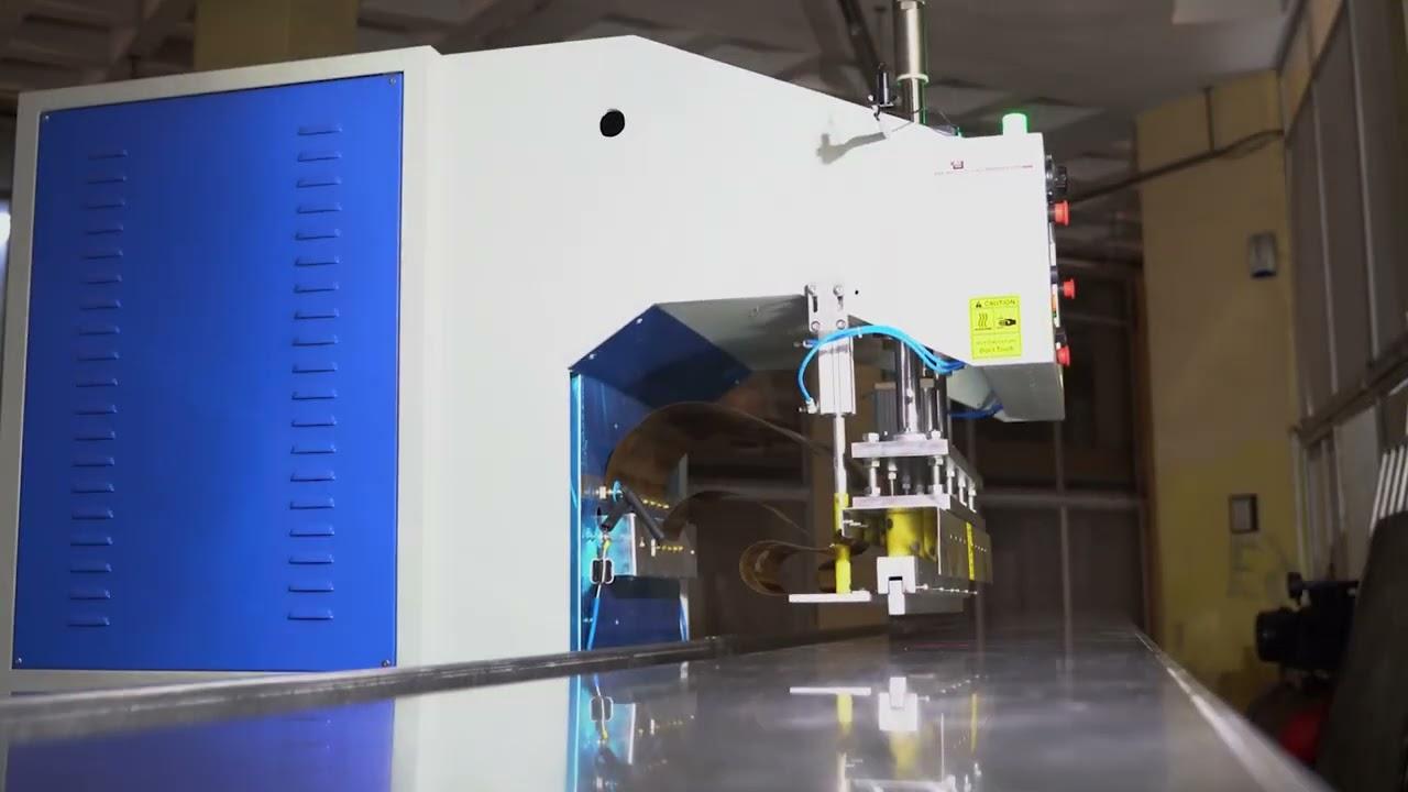
To improve RF welding seam strength and consistency, start with a compatible thermoplastic material, maintain uniform material thickness, and use properly designed electrodes. Establish a stable combination of RF power, welding time, electrode pressure, and cooling time through controlled testing. Keep the material clean and correctly positioned, inspect the tooling regularly, and verify weld quality using repeatable strength and leak tests where applicable.
The most effective improvements usually come from controlling the entire welding cycle rather than adjusting a single parameter. Excessive RF energy can damage the material, while insufficient energy or uneven pressure can produce incomplete bonding.
A seam must do more than hold two pieces of material together. Depending on the product, it may need to withstand tensile loads, repeated bending, internal pressure, handling, or exposure to environmental conditions.
Inconsistent seams can lead to several manufacturing problems:
Strong seams therefore depend on both mechanical performance and process repeatability. A seam that passes one strength test but varies significantly between production cycles may still be unsuitable for a high-volume manufacturing process.
Material selection is the starting point for a reliable welding process. RF welding works best with thermoplastics whose electrical properties allow them to generate sufficient heat in an alternating electric field.
PVC and suitable polyurethane formulations are commonly used because their polar molecular structures respond to RF energy. However, two grades within the same polymer family can behave differently during welding.
Plasticizers, fillers, pigments, coatings, reinforcement layers, and other additives may influence dielectric properties, heat generation, and material flow. A change in supplier or material formulation can therefore affect the established welding conditions.
Before optimizing the machine, confirm the following:
Do not assume that all thermoplastic materials can be joined using the same RF welding techniques. Conventional polyethylene and polypropylene, for example, are generally unsuitable for direct RF welding under standard conditions.
For new materials, conduct welding trials before approving them for production.
RF power determines how quickly the material heats during the welding cycle. If the energy input is too low, the interface may not soften sufficiently to form a sound joint. If it is too high, the material may overheat, degrade, thin out, or become damaged.
The relationship between power and seam strength is not linear. Increasing power may improve bonding up to a suitable operating range, but further increases can reduce quality.
When adjusting RF energy, consider:
A practical approach is to establish a baseline using a fixed material batch, tooling setup, and pressure setting. Adjust RF power in small, controlled increments while keeping the other variables constant. Record the results for each trial.
The objective is to find a stable operating window that produces acceptable seams, not simply the highest possible weld strength in a single sample.
Welding time determines how long RF energy is applied to the material. It works together with power to control the energy delivered during the heating stage.
If welding time is too short, the interface may not develop enough heat for proper bonding. If the cycle is too long, excessive heating can damage the material or create an unnecessarily wide weld.
To optimize welding time:
Avoid changing welding time and power simultaneously during initial troubleshooting. Making one controlled change at a time helps identify the actual cause of an improvement or defect.
Pressure helps maintain contact between the material layers while heat softens the joint area. Consistent pressure supports uniform bonding and helps prevent gaps, wrinkles, and localized weak points.
However, applying more pressure does not automatically create a stronger seam. Excessive pressure can squeeze softened material away from the joint, while insufficient or uneven pressure can leave areas incompletely bonded.
Check the following conditions:
For large electrodes or long seams, pay particular attention to pressure distribution. A seam may appear satisfactory at one end but remain weak at the opposite end if the tooling is misaligned or the clamping force is uneven.
Material thickness directly affects how the joint responds to RF energy. Thicker material, multilayer structures, and reinforced constructions may require different settings from thin, single-layer films.
Even when the nominal material thickness is correct, local variations can produce uneven heating. Overlapping folds, wrinkles, or inconsistent layer positioning can change the effective thickness at the weld.
To reduce these problems:
The layers should be aligned so that the electrode applies energy and pressure to the intended joint area. A wider overlap is not necessarily better; the overlap and weld width should follow the product design and validated requirements.
Electrode geometry determines where the RF field is concentrated and how pressure is applied to the material. Poorly designed or damaged tooling can cause uneven heating, inconsistent weld widths, arcing, and localized material damage.
The electrode should match the intended seam geometry and product requirements. Straight seams, curved contours, narrow seals, and complex patterns may require different tooling designs.
Inspect RF welding electrodes for:
The lower platen and barrier materials also need to be appropriate for the machine and application. Their condition can affect the electric field, insulation, and contact behavior.
For a new product, test the electrode design with the actual production material. Confirm that the resulting seam has the required width, strength, and sealing performance before releasing the tooling for mass production.
The heating stage is only part of the RF welding cycle. Once the RF energy is switched off, the material needs time to cool while the joint remains under suitable pressure.
If pressure is released too early, the softened seam may deform, separate, or lose its intended geometry before it has developed sufficient strength.
Cooling requirements depend on material formulation, thickness, seam geometry, and production conditions. A thick or heavily overlapped joint may behave differently from a thin film seam.
To improve consistency:
Do not use longer cooling time as a universal fix for weak seams. If the interface never received sufficient energy, cooling alone will not correct the underlying problem.
A structured process is more reliable than adjusting settings based only on appearance or operator intuition.
Select a known material batch and record its grade, thickness, layer construction, and supplier. Document the current machine settings, electrode configuration, overlap dimensions, and cycle sequence.
This baseline makes it easier to distinguish a machine problem from a material variation.
Check electrode alignment, tooling condition, pressure operation, and the machine's electrical and mechanical systems. Follow the manufacturer's maintenance instructions and safety procedures.
If a machine has unstable RF output or repeated arcing, investigate the underlying fault rather than compensating by increasing the power setting.
Run controlled trials to identify a suitable combination of RF power and welding time. Keep the material, pressure, tooling, and overlap consistent while testing.
Evaluate both under-welding and overheating. The target is a stable range that creates a sound seam without damaging the surrounding material.
After establishing a suitable heating condition, confirm that pressure is uniform and the joint remains held during cooling.
If seam strength varies across the electrode width, investigate alignment and pressure distribution before making further energy adjustments.
Visual inspection is useful, but it cannot prove seam strength on its own. Use appropriate mechanical and functional tests to determine whether the process meets the product specification.
Depending on the application, testing may include:
For products with specific regulatory or safety requirements, use the applicable test methods and acceptance criteria.
A good result from one sample is not enough to establish process consistency. Repeat the test under the same conditions and evaluate the variation between samples.
Where appropriate, test across different material batches, production shifts, or machine operating conditions. This helps identify whether the process is robust enough for regular production.
Once the process meets the acceptance criteria, record the approved operating window and inspection method.
Include the material specification, electrode configuration, RF power, welding time, pressure settings, cooling time, and relevant quality results. Define which changes require revalidation.
This documentation reduces dependence on individual operator experience and makes production easier to reproduce.
| Welding defect | Possible causes | Recommended checks |
|---|---|---|
| Weak or incomplete seam | Insufficient energy, unsuitable material, poor contact, short welding time | Verify material compatibility, power, time, pressure, and seam condition |
| Burn marks or material degradation | Excessive RF energy, prolonged heating, localized field concentration | Reduce energy input through controlled trials; inspect electrode geometry |
| Uneven weld width | Misalignment, inconsistent pressure, irregular material positioning | Check electrode alignment, platen condition, and locating fixtures |
| Arcing or pinholes | Contamination, damaged insulation, unsuitable settings, material or tooling issues | Stop and inspect the machine according to the manufacturer's safety procedure |
| Wrinkles in the seam | Poor material positioning, uneven feeding, inconsistent overlap | Improve alignment and material handling |
| Seam separation after cooling | Inadequate bonding, premature pressure release, material incompatibility | Review heating, pressure-holding, cooling, and material specifications |
| Inconsistent results between cycles | Material variation, unstable output, worn tooling, changing pressure | Check batch consistency, machine condition, and recorded process parameters |
These symptoms can have more than one cause. A defect should be diagnosed using controlled testing rather than assuming that one adjustment will solve every occurrence.
A peel or tensile test can measure the force required to separate a welded joint. The test configuration should reflect the product geometry and the purpose of the assessment.
Record the failure load and observe where the failure occurs. A joint that separates cleanly along the interface may indicate a different failure mechanism from one where the surrounding material tears.
The test method, specimen dimensions, pulling speed, and conditioning should remain consistent when comparing results.
Inspect the seam for continuous bonding, uniform width, wrinkles, burn marks, holes, and other visible defects. The weld bead can provide useful information about how the material flowed during the process.
Visual inspection should be combined with strength testing where seam performance is important. An attractive weld bead does not necessarily guarantee adequate mechanical strength or leak resistance.
For inflatable products, flexible tanks, medical bags, and other sealed products, mechanical strength alone may not be sufficient.
Use a suitable leak or pressure-retention test when the application requires airtight or watertight performance. Test conditions and acceptance limits should reflect the product's intended use and applicable specifications.
Consistency means that acceptable results can be reproduced over time. Track key measurements across multiple samples instead of relying on a single successful test.
Useful indicators include:
Statistical process control can help identify trends before they lead to widespread defects. Where suitable, establish control limits from actual production data rather than selecting arbitrary thresholds.
RF welding and hot air welding are different welding processes. The better choice depends on the material, product design, production volume, and quality requirements.
RF welding uses high frequency electromagnetic energy to generate heat inside compatible materials. Hot air welding uses heated air to soften the joining surfaces before pressure or another joining action brings them together.
RF welding can be well suited to repeatable, die-defined seams in compatible polar thermoplastics. It is often used for flexible products that require consistent weld patterns or sealed joints.
Hot air welding can be useful for suitable coated fabrics, membranes, and other materials where localized surface heating is appropriate. Its performance depends on material compatibility, air temperature, airflow, travel speed, contact pressure, and operator or automation control.
Neither process guarantees better results in every application. The correct welding technology is the one that can meet the product's strength, sealing, appearance, throughput, and cost requirements with repeatable results.
The benefits of RF welding depend on the application and material, but the process offers several practical advantages when correctly specified.
Because RF energy generates heat within compatible material, the process can form a joint without relying solely on heat conducted from the outside surface.
Purpose-designed electrodes can create consistent seam shapes and widths when the material, tooling, and machine settings remain controlled.
Suitable materials can form durable seams for products that need to contain air or liquids. The actual performance must be verified through appropriate testing.
RF welding can join compatible thermoplastic layers without adding adhesive to the welded interface. This can simplify some product designs, although the full product may still use coatings, reinforcement, or other joining components.
RF welding machines can be integrated into repeatable production workflows. Automated positioning, cycle control, and inspection can help reduce variation when properly implemented.
These benefits are not automatic. Material compatibility, machine condition, tooling design, and process validation determine whether they are achieved in practice.
Selecting suitable RF welding equipment begins with the product rather than the machine's rated power alone.
Consider the following factors:
Advanced RF welding systems may offer more extensive process controls, automation, and monitoring options. However, additional features do not replace correct material selection or process validation.
Before purchasing or upgrading an RF welding machine, ask the supplier to evaluate actual material samples and demonstrate that the proposed configuration can meet the product's acceptance criteria.
Use this checklist during process setup, troubleshooting, and routine production:
Confirm the material is compatible with RF welding.
Verify material thickness and formulation.
Check that the electrode surfaces are clean and correctly aligned.
Confirm uniform material overlap and positioning.
Establish stable RF power and welding time.
Verify electrode pressure and pressure distribution.
Maintain the required cooling time under pressure.
Inspect weld appearance and dimensions.
Perform mechanical and leak tests where applicable.
Repeat trials to verify process consistency.
Record approved settings and define revalidation triggers.
Follow the machine manufacturer's safety and maintenance procedures.
A documented checklist helps operators follow the same process and makes quality problems easier to trace.
Start by confirming material compatibility, then optimize RF power, welding time, electrode pressure, and cooling time through controlled trials. Check electrode alignment and material thickness, and verify the result using an appropriate peel, tensile, or functional test. Increasing power alone may damage the material rather than improve seam strength.
Weak seams can result from insufficient energy input, unsuitable material formulations, uneven pressure, inconsistent overlap, contaminated surfaces, or inadequate cooling under pressure. The correct response depends on the defect pattern and test results.
Yes. RF welding can produce airtight or watertight seams in suitable materials when the joint design and process are correctly controlled. However, a visually continuous seam is not proof of leak resistance. Use the appropriate leak test for the finished product.
PVC and suitable polyurethane formulations are among the most commonly used materials. Certain other polar thermoplastics may also be weldable under specific conditions. Compatibility depends on the exact formulation, thickness, and construction, so the actual material should be tested before production approval.
Not necessarily. Thickness can affect heat generation, pressure distribution, and the time needed to form a sound seam, but the relationship is not universal. Material formulation, electrode geometry, and machine characteristics also matter. Establish settings through controlled testing rather than applying a fixed power increase based on thickness alone.
Possible causes include excessive energy input, localized electric-field concentration, contamination, damaged insulation, or other machine and tooling problems. Stop the process if arcing or electrical faults occur, and follow the manufacturer's inspection procedure before resuming production.
Use approved material specifications, stable machine settings, repeatable fixtures, regular tooling inspections, and documented quality tests. Track seam strength and defect rates across production batches. Revalidate the process when material grades, thicknesses, electrodes, or significant machine settings change.
Neither method is universally better. RF welding is often suitable for compatible polar thermoplastics and repeatable die-defined seams. Hot air welding is useful for appropriate materials and applications that benefit from localized surface heating. Compare both against the product's material, seam geometry, production requirements, and validated performance.
Inspection frequency should reflect production volume, material behavior, tooling wear, defect history, and the machine manufacturer's recommendations. Check the electrodes during routine maintenance and whenever seam appearance or strength begins to change. High-volume production may require scheduled inspections and documented tooling-life criteria.
The process is ready when repeated trials meet the defined quality requirements and demonstrate acceptable variation under representative production conditions. Confirm seam strength, appearance, and leak resistance where applicable. Document the approved process window, inspection method, and conditions that require revalidation.
Improving RF welding seam strength and consistency requires coordinated control of material properties, RF energy, welding time, electrode pressure, tooling condition, and cooling. No single machine setting can compensate for every material or tooling problem.
Manufacturers should establish a controlled baseline, optimize one variable at a time, and verify results through repeatable mechanical and functional testing. Regular maintenance, consistent material handling, and documented process settings further reduce variation.
With the right material, properly designed RF welding equipment, and a validated process, manufacturers can produce more reliable seams, reduce avoidable defects, and maintain consistent product quality across production runs.