For cooperation and more details, feel free to email us or call directly for consultation.

Home > News & Blog > Knowledge > RF Welding Machine Mold and Electrode Design: A Practical Guide
RF welding machine mold and electrode design directly affect weld strength, seam consistency, product appearance, and production efficiency. A well-designed electrode defines the weld shape and width, distributes pressure across the joint, and helps the radio frequency (RF) field heat compatible thermoplastic materials evenly. The mold must also provide stable positioning, sufficient clearance, and a practical way to load and remove the finished part.
When designing tooling for RF welding machines, start with the material type and thickness, required seam geometry, product tolerances, and quality requirements. Then determine the electrode profile, weld width, pressure distribution, tool material, alignment method, and cooling conditions. Finally, validate the design through sample welding, destructive strength tests, leak testing where applicable, and repeatability checks across production cycles.
An RF welding mold is the tooling assembly that supports and positions the workpiece during welding. The electrode is the conductive tool component that shapes the weld area and transfers the high-frequency electric field to the material. Depending on the machine configuration, tooling may include an upper welding electrode, a lower counter-electrode or support plate, alignment features, insulating components, and fixtures for locating the product.
RF welding, also known as high frequency welding or dielectric welding, uses high-frequency electromagnetic energy to generate heat inside compatible materials. When pressure is applied, softened polymer layers fuse together. The joint is then held under pressure while it cools and solidifies.
The terms “mold” and “electrode” are sometimes used interchangeably in manufacturing discussions, but they are not always the same component. A mold or fixture may locate and support the part, while the electrode defines the active welding area. Understanding this distinction makes tooling specifications, maintenance, and troubleshooting more precise.
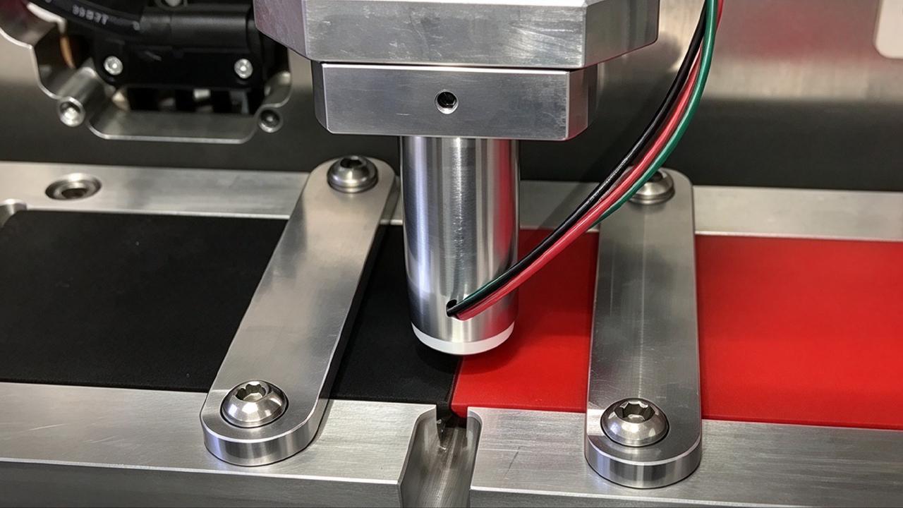
The electrode is more than a metal shape pressed against plastic film. Its geometry influences the distribution of the electric field, local heating, material compression, and the final seam profile. A design that works for one product may not produce the same results on a different material or machine.
The electrode profile determines the outline of the welded area. Straight bars are suitable for simple linear seams, while curved, circular, or custom-shaped electrodes can produce contours, pockets, channels, and complex product outlines.
The selected seam width should match the product's mechanical and sealing requirements. A narrow seam may reduce material waste and shorten the welding path, but it can also leave less tolerance for positioning errors. A wider seam may improve load distribution, although it can increase energy demand, squeeze-out, and the risk of uneven heating if the process is not tuned.
For products that must contain liquids or air, the weld path should form a continuous seal without unintended gaps at corners, intersections, or changes in direction.
Sharp or poorly finished edges can concentrate the electric field and increase the risk of localized overheating or arcing. Rounded edges may reduce stress concentrations, but excessive rounding can make the seam wider or less defined.
The correct edge profile depends on film thickness, material properties, desired seam appearance, and the machine's operating conditions. Designers should specify the profile on the tooling drawing rather than relying on a general instruction such as “polish the edge.”
Inspect the full perimeter of the electrode, especially corners, narrow sections, and transitions. Burrs, scratches, and inconsistent edge heights can cause repeatability problems.
If the active welding surface is not flat or correctly aligned, pressure may concentrate on a few areas instead of being distributed across the entire seam. The result can be a combination of over-welded and under-welded sections on the same part.
Check electrode height, parallelism, flatness, and alignment with the opposing tool. These requirements become more demanding when the product has long seams, multiple welding lines, or thin films that are sensitive to uneven compression.
For a complex electrode, inspection should include the complete active profile rather than only the mounting surface.
Corners and intersecting weld paths require particular attention. Electric-field concentration can vary around tight radii, and overlapping weld areas can receive more energy than adjacent sections.
To reduce defects:
For medical bags and other fluid-containing products, test the complete sealing perimeter, including the areas where tubing, ports, or additional layers meet the main seam.
Electrode material affects electrical performance, wear resistance, machinability, surface finish, and maintenance. The choice should reflect the RF generator, tooling geometry, production volume, and material being welded.
Copper alloys and other suitable conductive metals are commonly considered for RF welding electrodes because they can provide useful electrical conductivity and can be machined into detailed profiles. The best option depends on the tooling design and the machine's electrical and mechanical requirements.
When selecting a material, evaluate:
Do not select an electrode material based on conductivity alone. A material that is easy to machine may be less suitable for a high-wear application, while a harder material may be more difficult to modify during development. Confirm compatibility with the machine manufacturer before finalizing the tooling specification.
The lower mold or counter-electrode provides the reference surface against which the upper electrode operates. Its function is to support the workpiece, maintain alignment, and allow the welding force to act consistently across the intended joint.
The fixture should locate the product repeatably without stretching, folding, or distorting the film. Poor positioning can move the weld path away from the intended location, reduce the effective seam width, or cause the electrode to contact an unintended area.
Depending on the product, useful features may include locating pins, stops, pockets, guide edges, removable inserts, and templates. These features should hold the workpiece securely while allowing operators or automated handling equipment to load and unload it efficiently.
The support surface must match the electrode arrangement and the product's geometry. An unsuitable gap, uneven support, or excessive flexibility can allow the material to deform as pressure is applied.
For multi-layer products, the fixture should accommodate the complete stack-up, including films, reinforcing layers, tubing, valves, or other components. If material thickness varies across the part, the tooling design and welding process may need additional development to avoid uneven compression.
A mold that produces a good weld but traps the finished product can slow production and damage the seam during removal. Allow sufficient clearance for the part's shape, material flexibility, and any features that extend beyond the welded perimeter.
For complex products, check how the workpiece enters and exits the fixture. Include access for cleaning, inspection, and removal of scraps if the tooling performs both welding and trimming operations.
Material selection is a starting point for electrode design because different polymers respond differently to high-frequency electromagnetic energy.
RF welding is commonly used with compatible polar thermoplastics such as flexible PVC and certain grades of TPU, EVA, and other suitable polymers. Material formulation matters: two products carrying the same generic polymer name may behave differently because of plasticizers, additives, coatings, fillers, or reinforcement.
Polar molecules respond to the alternating electric field and generate heat through dielectric losses. This internal heating mechanism distinguishes RF welding from methods such as hot air, where heat is supplied from an external source.
Flexible PVC is widely used in RF welding because many formulations respond well to the RF field. Tooling should control the seam profile and prevent excessive material displacement during welding.
If the electrode is too aggressive or the process applies too much energy or pressure, the material may thin, flash, deform, or stick to the tooling. If the energy is insufficient, the seam may peel apart or fail a leak test.
TPU is used in inflatable products, fluid-handling products, wearable devices, and other applications requiring flexibility or abrasion resistance. Different TPU grades can have different processing windows, so a mold proven for one film should not automatically be approved for another.
For TPU-coated fabrics, consider the coating thickness, fabric structure, and orientation. The fixture should prevent wrinkles and movement without damaging the coating or leaving unwanted impressions.
Welding two different materials or layers of unequal thickness can be more difficult than joining identical films. The layers may respond differently to the electric field, soften at different rates, or compress unevenly.
Before finalizing the electrode, confirm the exact material stack-up. Sample tests should use production-representative materials rather than a substitute film with different electrical or mechanical properties.
Polyethylene (PE) and polypropylene (PP), in their standard forms, are generally not suitable for conventional RF welding because they are nonpolar. Alternative joining methods or specially engineered material systems may be required. Do not assume that all plastics can be joined using the same RF welding process.
Tooling geometry should reflect the function of the finished product, not just its external outline.
Medical bags may require long perimeter seals, internal channels, tubing connections, or port attachment areas. Electrode design must provide consistent sealing across these features without damaging thin films or obstructing fluid paths.
For medical devices, tooling development should be connected to the product's quality requirements. Depending on intended use, validation may include seal-strength testing, leak testing, visual inspection, dimensional checks, and process repeatability studies. Regulatory or quality-system requirements should be established by the device manufacturer.
A seam that looks uniform is not necessarily leak-tight. For products that contain fluids or gases, use suitable tests to confirm the finished seal meets the specified performance requirements.
Inflatable products, including pressure cuffs, need seams that withstand repeated loading and the specified internal pressure. Electrode geometry should follow the intended air chamber and channel layout, while the fixture maintains the correct position of the film or coated fabric.
Designers should pay attention to narrow channels, intersections, rounded corners, and connection points. These areas can behave differently from long, straight seams and should be included in prototype testing.
For PVC folders, covers, pouches, and similar products, appearance and production speed may be major requirements. The electrode should produce a clean seam with limited marking, distortion, or excess material.
When a product has decorative or functional patterns, the tooling drawing should distinguish the active welding profile from non-welding surfaces. This helps avoid unintended weld marks and simplifies inspection.
Good electrode design cannot compensate for an unstable machine or poorly controlled process. Weld quality depends on the interaction between tooling, material, RF power, pressure, welding time, and cooling under pressure.
Pressure brings the softened material layers into close contact and helps maintain the joint during cooling. Too little pressure may result in incomplete contact or inconsistent bonding. Too much pressure can squeeze material away from the seam, reduce its thickness, or distort the product.
Pressure should be evaluated across the complete welding area, not only at the center of the electrode. Parallelism, fixture rigidity, and press condition all affect how force is distributed.
The RF generator supplies high-frequency electromagnetic energy. The material's dielectric properties determine how efficiently that energy is converted into heat. Electrode geometry, spacing, material thickness, and the electrical characteristics of the complete setup influence the resulting field.
Excessive energy can cause overheating, discoloration, material thinning, or arcing. Insufficient energy can produce weak or incomplete welds. Adjust the process using controlled trials and the machine manufacturer's procedures rather than relying on visual appearance alone.
Cycle times include more than the period when RF energy is applied. Depending on the machine and product, the overall cycle may include loading, clamping, pre-pressure, RF welding, cooling under pressure, opening, and unloading.
A complex mold may improve product quality but slow loading or removal. Conversely, a fixture designed for fast handling may introduce positioning errors if it does not locate the material reliably.
Measure the full cycle during production trials. Compare both cycle time and the percentage of acceptable parts, because a faster cycle is not an improvement if it creates more leaks, weak seams, or rejected products.
Possible causes: Poor electrode parallelism, uneven support, inconsistent material thickness, or an unsuitable weld profile.
What to check: Inspect the complete seam, verify alignment, and test the fixture with the actual production material stack-up. Adjust one variable at a time during trials.
Possible causes: Sharp edges, burrs, contamination, unsuitable spacing, excessive RF energy, or material conditions outside the validated process window.
What to check: Stop the machine and follow the manufacturer's safety procedure before inspecting tooling. Check the electrode surface, clean the tooling as specified, and review the process settings and material condition.
Possible causes: Excessive pressure, an unsuitable electrode profile, too much RF energy, or a mismatch between seam geometry and material thickness.
What to check: Review pressure and welding time together with the seam profile. Do not assume that increasing seam width or reducing energy alone will solve the problem.
Possible causes: Abrupt changes in electrode geometry, poor positioning, uneven pressure, or a local difference in electric-field distribution.
What to check: Inspect corner radii and intersections, verify alignment, and perform targeted leak or strength tests at the affected locations.
Possible causes: Tool wear, changes in film formulation or thickness, loose fixtures, contamination, or variation in machine setup.
What to check: Establish a tooling inspection schedule, record material lot details, maintain documented process settings, and compare results over multiple runs.
A structured development process helps reduce repeated machining and trial-and-error adjustments.
When requesting a mold or electrode quotation, provide enough detail for the supplier to assess both the tooling and the welding process.
Include the following information:
If some information is not yet available, send the product sample, material data sheet, and a clear description of the intended use. The tooling supplier can then identify which details need to be confirmed before the final design is approved.
A mold should not be approved solely because it produces a visually acceptable sample. A proper evaluation checks whether the tooling can repeatedly produce parts that meet the product specification.
Dimensional inspection: Confirm seam width, position, shape, and relevant product dimensions.
Visual inspection: Look for burn marks, wrinkles, flash, pinholes, incomplete seams, and unwanted impressions.
Strength testing: Use an appropriate peel, tensile, burst, or other test method for the product and joint design.
Leak testing: For medical bags, inflatable products, and fluid or gas containers, use a test method suited to the product's intended operating conditions.
Repeatability testing: Run enough samples to evaluate normal process variation. Include start-up conditions and, where appropriate, multiple material lots.
Maintenance review: Confirm that the electrode can be cleaned, inspected, aligned, and repaired without compromising its active geometry.
The acceptance criteria should be defined before testing begins. For medical devices and other regulated products, the manufacturer should determine the required validation and documentation in accordance with applicable quality and regulatory requirements.
The electrode is the conductive component that creates the active welding profile and couples RF energy into the workpiece. The mold or fixture may include the electrode as well as supports, locating features, and other components that position the product. In some machine designs, the terms are used more broadly, so the tooling drawing should identify each component clearly.
There is no single best material for every application. Suitable conductive metals, including selected copper alloys, may be used depending on electrical requirements, geometry, wear, machinability, and production volume. The choice should be confirmed against the machine design and the intended welding process.
Seam width depends on the material, film thickness, product design, expected load, sealing requirements, and acceptable appearance. A wider seam is not automatically stronger or more reliable. Establish the width through engineering requirements and prototype testing.
Potential causes include burrs, sharp edges, contamination, poor alignment, unsuitable spacing, excessive RF energy, or material variation. Stop the process and follow the machine manufacturer's safety procedure before inspecting the tooling. Correct the underlying cause instead of simply shortening the welding time.
Sometimes, but this should not be assumed. PVC and TPU formulations can respond differently to RF energy and pressure. The electrode geometry may be reusable, while the process settings and validation requirements differ. Test each production material and confirm that the tooling meets the required weld specification.
Electrode geometry affects the area being welded, the distribution of energy and pressure, and how quickly the product can be positioned and removed. A poorly designed tool may require longer welding or cooling, or create defects that lead to rework. Evaluate total cycle time alongside yield and seam performance.
RF welding is widely used for compatible thermoplastic components in medical applications, including certain fluid bags and inflatable devices. Suitability depends on the exact material, product design, and intended use. Manufacturers should validate seal strength, leak performance, process repeatability, and any applicable regulatory requirements.
RF welding and hot-air welding use different heating mechanisms. RF welding generates heat inside suitable dielectric materials through a high-frequency electric field, while hot air supplies heat externally. The best method depends on material compatibility, product geometry, seam requirements, and production conditions.
Start with compatible materials and a correctly designed electrode and fixture. Maintain alignment, keep tooling clean, control pressure and RF energy, and validate welding and cooling times. Use documented inspection and testing methods to identify changes before they lead to larger batches of defective parts.
Provide a product drawing or sample, material type and thickness, required seam dimensions, performance criteria, target output, and the RF welding machine model. Photos or drawings of the existing tooling can also help. For medical bags or other sealed products, clearly state the required leak or strength tests.
RF welding machine mold and electrode design should begin with the product's material, seam geometry, and performance requirements. Electrode profile, edge finish, flatness, fixture support, and workpiece positioning all affect how the RF welding process behaves in production.
A practical development process combines accurate tooling drawings with controlled sample welding, strength or leak testing, and repeatability checks. By evaluating the mold and the welding parameters as one system, manufacturers can improve seam consistency, manage cycle times, and reduce avoidable defects across RF welding machines.