For cooperation and more details, feel free to email us or call directly for consultation.

Home > News & Blog > Knowledge > RF Welding Machine Troubleshooting: Common Defects and Solutions
RF welding machine defects are usually caused by an imbalance between RF energy, pressure, welding time, material condition, electrode alignment, and cooling. Common problems include weak welds, incomplete sealing, excessive flash, burn marks, arcing, wrinkles, and inconsistent seal strength.
A practical troubleshooting sequence is to check the base material first, then inspect the weld area and tooling, verify the RF welding settings, check pressure and alignment, and finally review the machine's electrical and mechanical condition. Do not increase RF power immediately when a weld is weak, because the underlying problem may be material variation, poor contact, insufficient pressure, or an incorrect electrode profile.
RF welding troubleshooting is the systematic process of identifying and correcting defects that occur during an RF welding or RF sealing operation.
RF welding uses radio frequency electromagnetic energy to heat suitable thermoplastic materials at the weld interface. When the material reaches an appropriate softened state and pressure is maintained, the layers fuse together. After cooling, the joint forms the finished weld.
Unlike conventional hot-air welding, where an external hot-air source supplies heat to the surface, RF welding generates heat within the material through RF energy. This makes electrode design, material properties, pressure distribution, and machine settings important parts of the welding process.
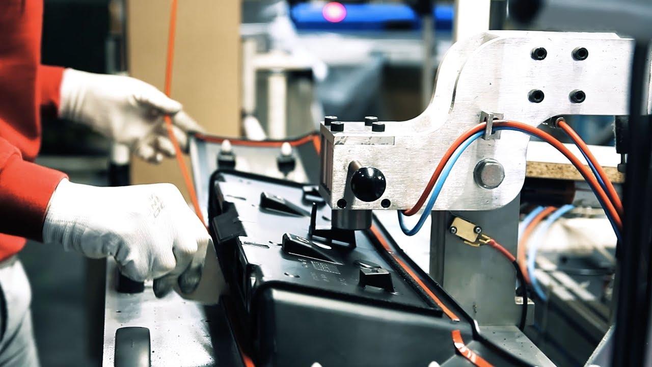
The basic RF welding sequence is straightforward:
The result depends on the relationship between material properties, RF energy, pressure, welding time, cooling time, and tooling geometry. Changing one parameter can affect the others.
A weak weld is one of the most common RF welding problems. The seam may look acceptable but fail during peel, tensile, burst, or leak testing.
Possible causes include:
Start by inspecting the material and weld area. Confirm that the base material is suitable for RF welding and that the actual material thickness matches the approved specification.
Next, check whether the electrodes are parallel and whether pressure is distributed consistently. If the tooling is correct, gradually evaluate RF energy and welding time through controlled trials.
Avoid simply increasing power until the weld “looks stronger.” Excessive RF energy can overheat the polymer and produce a seam that appears strong but has reduced mechanical integrity.
Incomplete sealing occurs when part of the intended weld area does not bond properly. This is particularly problematic for products that need an airtight or liquid-tight seal.
Inspect the entire perimeter rather than focusing only on the failed section. Look for wrinkles, foreign particles, material distortion, or areas where the electrode does not contact the material evenly.
If only one section repeatedly fails, compare that location with the electrode geometry. A localized problem often points to tooling or pressure distribution rather than an overall RF power problem.
For RF sealing applications, perform the appropriate leak test after making adjustments. Visual inspection alone cannot confirm that a sealed product is leak-free.
Flash is excess softened material pushed outside the intended weld profile. A small amount may occur depending on the material and process, but excessive flash can affect appearance, dimensions, and seal performance.
Inspect the weld profile and compare the actual seam with the tooling drawing. Check whether the material is being compressed beyond the intended weld area.
Reduce the process variables gradually rather than changing several settings at once. If the same flash pattern appears repeatedly, review the electrode design and pressure distribution.
Burn marks indicate that the material has received excessive localized heating or that the welding conditions are producing an undesirable concentration of energy.
First inspect the electrode surfaces for scratches, burrs, contamination, or damaged edges. Check whether the burn occurs at the same position on every part.
If the defect follows a particular tooling feature, the electrode geometry may need modification. If the entire weld is overheating, review RF energy, welding time, pressure, and material thickness.
Do not continue production with repeated arcing or severe burning. Follow the welding machine manufacturer's safety procedures before inspecting or servicing the equipment.
Arcing is an electrical discharge that can occur when the RF field becomes concentrated or when conditions around the weld area are unsuitable.
Common contributors include:
Stop the process according to the machine's operating and safety instructions. Inspect the tooling, insulating components, material placement, and weld area.
Look for carbonized marks because previous arcing can leave conductive contamination that makes subsequent arcing more likely.
The solution may involve cleaning, repairing the electrode, correcting alignment, changing the tooling geometry, or adjusting process parameters.
A weld may be strong in one section and weak in another. This usually suggests that RF energy, pressure, material thickness, or electrode geometry is not consistent across the complete joint.
Electrode flatness: An uneven electrode can change local pressure and RF coupling.
Press parallelism: The upper and lower tooling should meet consistently.
Fixture support: Flexible or unstable support can change pressure distribution.
Material thickness: Different thicknesses can respond differently to the RF field.
Electrode geometry: Long weld paths, sharp corners, intersections, and narrow sections may behave differently from straight sections.
When troubleshooting this defect, map the failed locations. A pattern can provide useful information about the source of the problem.
Wrinkles can prevent uniform contact between material layers and lead to incomplete or weak welds.
Improve the way the workpiece is positioned before the press closes. The fixture should locate the material without unnecessarily stretching or distorting it.
For thin films, even a small fold can affect the final weld. If wrinkles occur repeatedly in the same location, review the mold or fixture design rather than changing RF power alone.
Material sticking can slow production and damage the welded product during removal.
Inspect and clean the tooling according to the equipment manufacturer's instructions. Check the electrode surface for damage or material buildup.
Then review RF energy, pressure, and welding time. If sticking remains after process optimization, the electrode surface treatment or tooling design may need to be evaluated.
A weld can have the correct strength but still fail because it is positioned incorrectly on the finished product.
This problem is often related to the fixture rather than the RF generator.
Check the locating system and compare the actual product position with the approved tooling drawing.
For high-volume RF welding, repeatable positioning becomes increasingly important because small loading variations can create dimensional problems over hundreds or thousands of cycles.
When the same machine and tooling produce different seal strength from one production run to another, investigate material and process variation.
The base material may have changed in:
A material change can alter the way RF energy is absorbed and converted into heat.
Record material lot numbers alongside machine settings and quality results. Compare failed and approved batches rather than changing machine settings without identifying the source of variation.
For demanding RF sealing applications, maintaining a defined material specification and documented process window can make troubleshooting much faster.
RF energy controls how much electromagnetic energy is delivered to the weld area. Too little energy can produce incomplete bonding, while too much can cause overheating, flash, or arcing.
Make adjustments gradually and evaluate the resulting weld with the appropriate quality test.
Longer welding time generally increases the amount of energy delivered to the material. However, longer is not automatically better.
If the weld reaches the required bonding condition early, additional heating can increase the risk of material degradation.
Pressure ensures close contact between the material layers and maintains the joint during the process.
Too little pressure may produce poor contact. Too much pressure may cause material displacement, flash, or excessive thinning.
The material should remain under suitable pressure while the weld cools. Releasing pressure too early can allow the joint to separate or deform before it has developed sufficient strength.
The upper and lower tooling must work together. Misalignment can produce uneven pressure and inconsistent RF coupling.
Check alignment whenever the defect is localized or when one side of a weld consistently performs differently from the other.
RF welding is one of several methods used for joining thermoplastic materials.
Hot-air welding supplies heat from an external source. RF welding uses electromagnetic energy to generate heat within suitable material.
Hot air can be useful for some films, coated fabrics, and three-dimensional seams, while RF welding is well suited to compatible dielectric materials where controlled tooling can define the weld shape.
Conventional heat sealing normally heats the material through heated tooling or another external heat source. RF welding generates heat within the material through an electromagnetic field.
The best method depends on material properties, product geometry, seam requirements, output, and quality specifications.
When an RF welding machine begins producing defective parts, use this sequence:
Step 1 — Inspect the material
Confirm the polymer, thickness, surface condition, material lot, and layer arrangement.
Step 2 — Inspect the weld area
Look for contamination, wrinkles, folds, moisture, scratches, or incorrect positioning.
Step 3 — Inspect the tooling
Check electrode condition, flatness, alignment, edge geometry, insulation, and fixture support.
Step 4 — Review machine settings
Record RF energy, welding time, pressure, cooling time, and other relevant parameters.
Step 5 — Identify the defect pattern
Determine whether the defect occurs everywhere, along one side, at corners, at intersections, or only in specific product areas.
Step 6 — Make one controlled change
Change one process variable at a time where possible. This makes it easier to determine which adjustment produced the improvement.
Step 7 — Verify with testing
Use the appropriate strength, dimensional, leak, burst, or visual inspection method for the product.
Step 8 — Document the result
Record the final settings, material lot, tooling condition, test results, and corrective action.
Troubleshooting becomes easier when the production process is controlled before defects appear.
Use approved materials with controlled thickness and formulation. Keep material specifications and lot information available for production traceability.
Check electrode surfaces, alignment, flatness, fixture components, and insulation. Remove contamination before it affects production.
Instead of defining only one machine setting, establish acceptable ranges for RF energy, pressure, welding time, and cooling time based on product testing.
Periodic destructive testing can reveal changes that are not visible during routine inspection.
Record defect type, material lot, tooling revision, machine settings, and production date. Patterns often become easier to identify when historical data is available.
Some defects can be corrected through normal process adjustment, while others require technical inspection.
Contact the equipment manufacturer or qualified service personnel when:
Electrical and RF systems can contain hazardous voltages and stored energy. Maintenance should be performed only by qualified personnel following the equipment manufacturer's procedures.
Weak RF welds can result from insufficient RF energy, inadequate pressure, unsuitable material, poor electrode alignment, contamination, incorrect welding time, or insufficient cooling. Check material and tooling before increasing RF energy.
Burn marks can occur when the weld area receives excessive localized RF energy. Sharp electrode edges, contamination, poor alignment, unsuitable tooling geometry, and excessive welding time can also contribute.
Arcing can result from sharp tooling edges, contamination, incorrect clearances, excessive RF energy, damaged insulation, or material positioned incorrectly. Follow the machine safety procedure before inspecting the tooling.
Start with consistent material, stable fixture positioning, correctly aligned electrodes, and controlled RF energy, pressure, welding time, and cooling. Regular seal-strength or leak testing can help detect process drift.
Yes. Variations in thickness, formulation, coatings, additives, surface condition, or material lots can change RF heating behavior and final seal strength. Material control should therefore be part of RF welding troubleshooting.
Yes. In industrial manufacturing, RF welding and high frequency welding are commonly used to describe the same general dielectric welding technology. The process uses high-frequency electromagnetic energy to heat compatible thermoplastic materials.
Shielding gas is generally not a fundamental requirement for conventional RF welding because the process does not rely on an open molten-metal arc or an externally heated atmosphere. If a particular machine or application uses shielding gas, follow the equipment and process specifications rather than assuming it is required for RF welding.
RF welding can be used for suitable thermoplastic components in medical applications, including certain bags, pouches, tubing assemblies, and other devices. The exact material, tooling, process validation, quality requirements, and applicable regulatory requirements must be established for the specific product.
Control material thickness, workpiece positioning, electrode condition, pressure, RF energy, welding time, and cooling time. A documented setup procedure and regular tooling inspection can also reduce variation between production runs.
Check whether the material, tooling, and machine settings have changed. Then inspect the weld area for contamination or positioning problems and examine the electrode for damage or misalignment. Sudden defects are often easier to diagnose by comparing the current setup with the last known-good production condition.
Effective RF welding machine troubleshooting starts with understanding the relationship between the material, tooling, pressure, RF energy, and welding time. Weak welds, incomplete RF sealing, flash, burn marks, arcing, wrinkles, and inconsistent seal strength can have very different causes even when they appear similar on the finished product.
A reliable troubleshooting method is to inspect the base material, examine the weld area and electrode, verify pressure and alignment, review the RF welding parameters, and confirm the result through appropriate quality testing. Keeping these factors controlled helps RF welding equipment produce consistent joints while reducing unnecessary machine adjustments, material waste, and production interruptions.